LASER diodes are nothing more than semiconductor devices equipped with a resonant optical cavity and appropriate mirroring that have the effect of the population inversion of excited atoms, which when returning the electrons to the original levels of energy produce the radiation that characterizes LASER .
As shown in Figure 1, these devices behave like ordinary diodes, but need a strong current to operate.
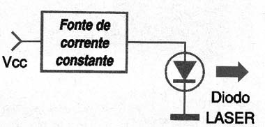
This current must be controlled so that the overload of the device does not occur, which requires the use of a special device.
The semiconductor coolers are based on the Peltier effect, as shown in figure 2.
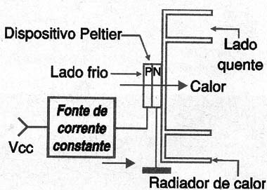
When a current flows through a semiconductor junction it "draws" the heat from one side of the material and transports it to the other. Then we have one face of the device that cools and the other one that heats up.
With constant circulation of a current through the device, the heat can be withdrawn from one side of the device and dissipated from the other, whereby a suitable radiator is placed therein.
Devices of this type have been used both in cooling electronic circuits, mounted directly on high power components such as microprocessors and microcontrollers, as well as in consumer applications such as automotive or battery-powered refrigerators and solar panels.
Peltier or Thrmoelectric Coolers (TEC) behave like semiconductor diodes, requiring constant current sources for their power supply, with configurations very similar to those used to power the LASER diodes.
Next, based on Burr-Brown's SBEA001 Application Report, we bring to the reader five practical circuits, three of which are for excitation of linear mode and two for the excitation of LASER diodes,
Laser Diode Driver - 1
The circuit shown in figure 3 serves to power a laser diode of signal or to directly excite it. The circuit is based on a Howland current pump with a transistor that serves as an amplifier.
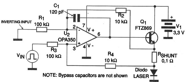
The circuit is based on an operational CMOS OPA350 amplifier that through a feedback circuit senses the current in the LASER diode in order to provide its control. The circuit measures the voltage drop at the shunt resistor (Rshunt) which is connected in series with the LASER diode.
The scale factor in this circuit is 1 V which corresponds to a current of 1 A. Other scaling factors can be used according to the characteristics of the LASER diode. The V in / Iout scale factor can be calculated by the following formula:
Vin / Vout = (R3 / R4) x Rshunt and in this circuit R1 = R3 and R2 = R4
In figure 4 we have a graph showing the output current as a function of the power dissipated by the transistor, for a supply voltage of 3.3 V.
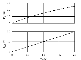
The transistor used in the design comes in the case of SOT-223 case where the assembly is made such that most of the heat generated is dissipated by the copper tracks of the printed circuit board. Of course, transistors of equivalent characteristics can be used.
Laser Diode Driver - 2
The circuit shown in Figure 5 consists of a voltage controlled current source. The circuit is characterized by the possibility of powering a very low-noise LASER diode, and can also be used as PWM power control.
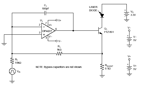
Note that the circuit requires symmetrical 5 V voltages for the operational amplifier and also 3.3 V for the LASER diode itself.
The circuit uses a very low noise OPA227 operating amplifier, driving a power transistor. This transistor will dissipate power of the order of 1.5 W with a 3.3 V supply. The graph of figure 6 shows the dissipation as a function of the input voltage with 3.3 V supply.
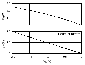
In the same way as in the previous circuit, the scale factor, ie the ratio between the input voltage (Vin) and the output current (Vout), can be changed. The formula used can be:
Vin / Vout = (R1 / R2) x Rshunt
Linear Driver for TEC
The circuit shown in figure 7 is for the excitation of a semiconductor cooler with a current of +/- 2 A.
The circuit operates with a single 5 V supply by energizing the refrigerator transducer with a constant current. One feature of this circuit is the assembly of the bridge transistors in order to obtain a BTL configuration that reverses the current direction.
See that the device used has a circuit equivalent to two diodes in parallel and in opposition thereto its power can be made with currents circulating in both directions.
The circuit shown has an input offset of half the supply voltage, that is, +/- 2.5 V which allows the amplifiers to oscillate in both directions of the power supply thus using a single source.
As in the previous circuitry, there is a shunt resistor in series with the cooling device which is used to provide the control signal which returns the circuit.
The circuit is designed to power 1 ohm to 2 Ω TECs, operating with a 5 V power supply. The current in the scrubber element will be 2 A.
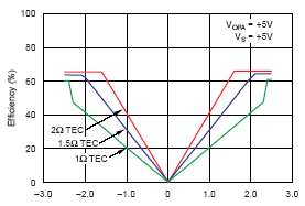
In figure 8 we have a graph that shows the efficiency of the circuit with several types of TEC in the resistance range indicated.
Driver Linear of TEC - 2
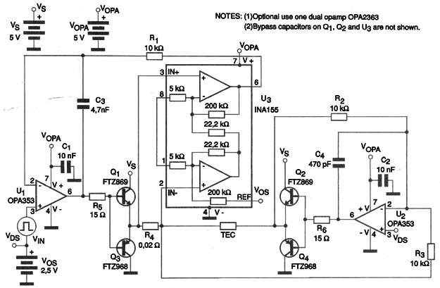
The circuit shown in Figure 9 provides currents of +1.5 A and -1 A to a TEC. The circuit uses a small signal amplifier that can operate with a single 5 V source.
The power stage that directly feeds the cooler (TEC), however, is powered by a 3.3 V voltage. The cooler operating mode is in constant current with a bridged configuration (BTL).
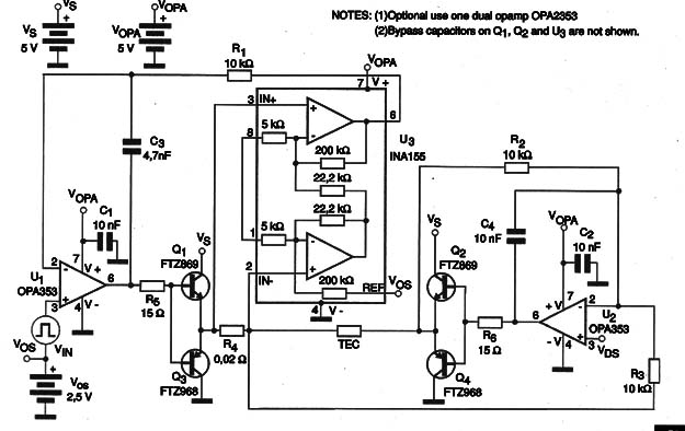
The Vin input voltage is amplified by an operational (U1) RR CMOS amplifier of type INA155, which is specially designed for instrumentation applications. The amplifier U3 has the purpose of sensing the current in the cooling element, providing the control signal for U1.
The circuit is calculated for a current of 1 A, but the values of the components can be changed to other currents. Simply change the scale factor using the formula:
Vin / Iout = Av x R4 where Av is the gain in V / V.
In figure 10 we have the output current curve for input voltage for different resistor TECs.
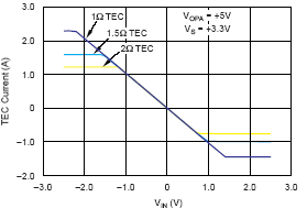
Note that power to the control circuit is made with 5 V and power circuit power is supplied with 3.3 V.
Driver Linear of TEC - 3
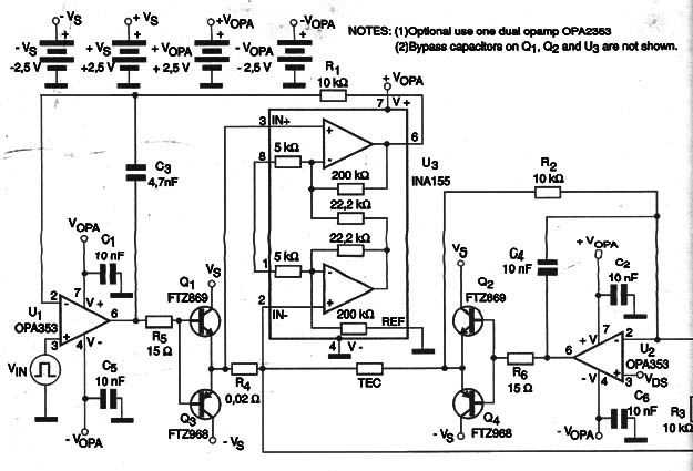
Finally we have in Figure 11 a linear driver for semiconductor Cooler capable of supplying a current of +/- 2.5 A with load resistors of 1 to 2 Ω.
The circuit operates with a symmetrical source of +/- 2.5 A, giving the cooler a constant current, which is highly desirable in powering this type of device.
Using a symmetric source an offset voltage is not required to cause the amplifier to have outputs traveling both polarities. A level transposition circuit is required to interface simple voltage fed circuits.
In this circuit we have an operational CMOS RR amplifier that contains a simple power stage in class B, driving a bridge circuit with four power transistors.
The circuit contains a step which senses the current in the load in order to provide a control signal for the power steps. The calculation of the current in the load or scaling factor is calculated in the same way as we saw in the previous circuits.
In the same way as in the previous circuits, the current in the TEC elements can be controlled in the same range from the input signal.
Note that the current in these elements is directly dependent on the control voltage applied to the input.
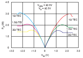
In figure 12 we have a graph where we show the power dissipated by the transistors for several input voltages and with resistance TECs between 1 and 2 Ω.
Conclusion
LASER Diodes and TECs (Semiconductor Coolers) require constant current in their power supply.
In the most critical applications, this current must have absolute control, requiring appropriate circuits. The circuits we have seen are examples that can be used in practical projects.
More information can be obtained on the company's own website in the Application Note which details these and other circuits.
